THE RESURRECTION OF
AT-11 41-27603
This page was last updated on
January 9th, 2006
The latest updates are at the
bottom of the page in chronological order.
To skip to the latest update
click here
This is a page that will show the restoration of a 1942 Beech
AT-11 from the beginning to its first flight. Vintage Aircraft was chosen to
bring this great old Warbird back from the bone yard and make her fly once
again. We taken several rare Twin Beech's from the scrap pile and put them back
in the air where they belong. This is the first time that we have documented
such a project on the web. Please stay tuned as we will update this page
throughout the restoration. Maybe we will set up a web cam if I can find the
time to figure out
how to do so.
ALL OF THE IMAGES ARE THUMBNAILS SO JUST
CLICK ON ONE TO SEE A LARGER PICTURE
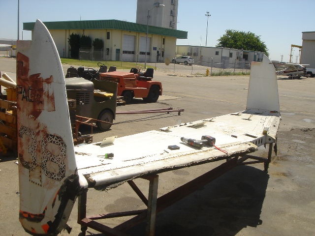
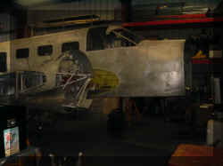
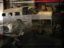
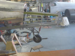
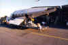 The first step is to bring the project home. Not a simple task with a Twin
Beech. This is the AT-11 when she arrived in Stockton. This is our trailer that
we built especially for transporting Twin Beech airframes. For more information
about moving the Twin Beech click here.
The first step is to bring the project home. Not a simple task with a Twin
Beech. This is the AT-11 when she arrived in Stockton. This is our trailer that
we built especially for transporting Twin Beech airframes. For more information
about moving the Twin Beech click here.
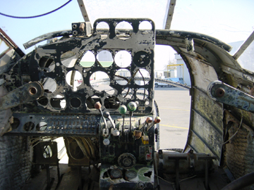
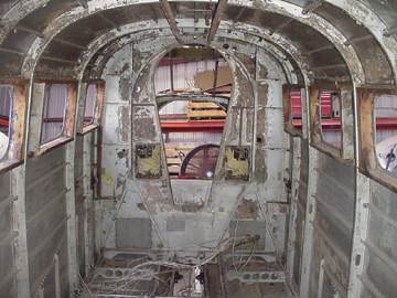
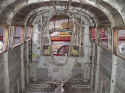
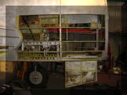
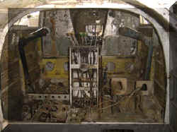
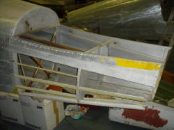
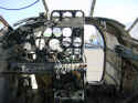 This is the before picture of the cockpit. Stay tuned for changes.
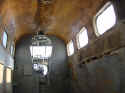 I am sure that the wood interior was beautiful at one time. After the basic
airframe inspection is complete the work begins. The first part is relatively
simple...the disassembly.
I am sure that the wood interior was beautiful at one time. After the basic
airframe inspection is complete the work begins. The first part is relatively
simple...the disassembly.
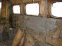
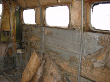
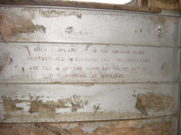
 As the interior and old insulation is removed
some interesting things show up. In the center of the picture is an original
warning stencil which reads "CAUTION WHEN AIRPLANE IS ON THE GROUND MAKE
CERTAIN ALL PERSONNEL AND OBSTRUCTIONS ARE CLEAR OF THE BOMB BAY DOORS BEFORE
DOOR CONTROL IS OPERATED". Even though she has been heavily modified as a
little air liner some of her old military history is still visible. I believe
that it is extremely important to document all of these little details and to
make them a part of the aircraft's records. So many of these little details are
wiped out and lost for ever when striping paint. Even if the customer
does
not want an authentic restoration but a custom built aircraft these details
should be recorded. Maybe the next owner will want to bring the aircraft back
into a stock and authentic configuration where these small details will be quite
valuable. Remember if we do our job right, these aircraft will be around long
after we are. We are just temporary care takers of these historic treasures.
As the interior and old insulation is removed
some interesting things show up. In the center of the picture is an original
warning stencil which reads "CAUTION WHEN AIRPLANE IS ON THE GROUND MAKE
CERTAIN ALL PERSONNEL AND OBSTRUCTIONS ARE CLEAR OF THE BOMB BAY DOORS BEFORE
DOOR CONTROL IS OPERATED". Even though she has been heavily modified as a
little air liner some of her old military history is still visible. I believe
that it is extremely important to document all of these little details and to
make them a part of the aircraft's records. So many of these little details are
wiped out and lost for ever when striping paint. Even if the customer
does
not want an authentic restoration but a custom built aircraft these details
should be recorded. Maybe the next owner will want to bring the aircraft back
into a stock and authentic configuration where these small details will be quite
valuable. Remember if we do our job right, these aircraft will be around long
after we are. We are just temporary care takers of these historic treasures.
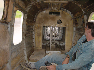
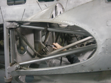
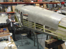
 Rick surveys the job ahead...
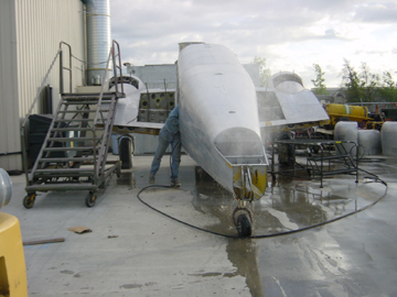
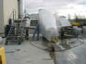 and the cleaning begins. First the airframe is steam cleaned to remove 50 years
of dirt, sand, grease, tools and other parts.
and the cleaning begins. First the airframe is steam cleaned to remove 50 years
of dirt, sand, grease, tools and other parts.
 Then she comes inside the shop where the airframe is thoroughly cleaned.
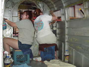
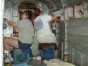 We even got the girls involved. Not to be sexist but boy can they clean!
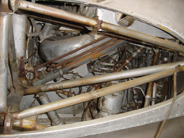
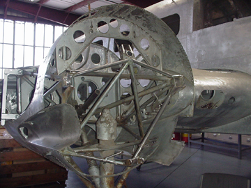
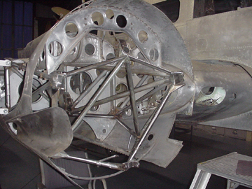
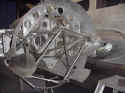
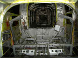
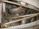 This is the inside of the right engine nacelle looking through the wing attach.
In this shot you can see the main spar truss assembly that is made from steel.
The spar has a coating of rust that needs to be cleaned. For the restoration in
general, and to gain access to the complete spar, the components are removed,
tagged, photographed and logged.
This is the inside of the right engine nacelle looking through the wing attach.
In this shot you can see the main spar truss assembly that is made from steel.
The spar has a coating of rust that needs to be cleaned. For the restoration in
general, and to gain access to the complete spar, the components are removed,
tagged, photographed and logged.
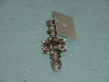
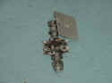 Here is an example of a removed part. This is the upper main gear chain sprocket
from the right gear well and is tagged as number 175. Other photos were taken
that show the whole assembly that the part was removed from will help greatly
when it comes time to replace the restored part. The part is logged into the
database where the picture is stored so quick reference can be made to aid in
the restoration. This not only gives us a good record of the work but serves as
a valuable tool for the restoration technician. Our customer is given a
new CD on a regular basis which is full of the photos showing the work and
progress. The date stamps on the digital image also verify when the work was
accomplished so the customer can keep track of progress. This is a wonderful
system that I have developed which was made possible by the digital camera. If I
never develop a roll of film again I will be happy.
Here is an example of a removed part. This is the upper main gear chain sprocket
from the right gear well and is tagged as number 175. Other photos were taken
that show the whole assembly that the part was removed from will help greatly
when it comes time to replace the restored part. The part is logged into the
database where the picture is stored so quick reference can be made to aid in
the restoration. This not only gives us a good record of the work but serves as
a valuable tool for the restoration technician. Our customer is given a
new CD on a regular basis which is full of the photos showing the work and
progress. The date stamps on the digital image also verify when the work was
accomplished so the customer can keep track of progress. This is a wonderful
system that I have developed which was made possible by the digital camera. If I
never develop a roll of film again I will be happy.
 Here Rick is cleaning the spar down to the bare metal. The spar truss is a one
piece welded structure that is 17 feet wide. This has been and continues to be a
weak area of the Beech 18. This spar can develop cracks and over time rust can
diminish the strength of the spar. A thorough visual and x-ray inspection is
required to verify airworthiness of the structure. For more information about
spars click here and scroll down
to the spar paragraph.
Here Rick is cleaning the spar down to the bare metal. The spar truss is a one
piece welded structure that is 17 feet wide. This has been and continues to be a
weak area of the Beech 18. This spar can develop cracks and over time rust can
diminish the strength of the spar. A thorough visual and x-ray inspection is
required to verify airworthiness of the structure. For more information about
spars click here and scroll down
to the spar paragraph.
 A thorough cleaning, priming and painting will ensure that this spar, and
consequently the rest of the aircraft, will last another 50 years. this photo
shows the special primer that we use on the steel truss.
A thorough cleaning, priming and painting will ensure that this spar, and
consequently the rest of the aircraft, will last another 50 years. this photo
shows the special primer that we use on the steel truss.
 The truss is then sprayed with a top coat of aluminum pigmented paint just as it
was done at the factory. Later the original factory stenciling will be painted
on the spar exactly as it was originally done.
The truss is then sprayed with a top coat of aluminum pigmented paint just as it
was done at the factory. Later the original factory stenciling will be painted
on the spar exactly as it was originally done.
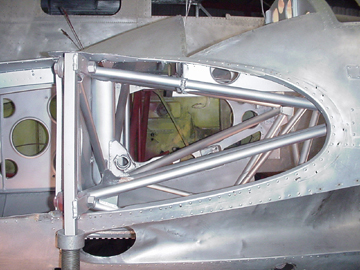
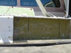
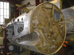
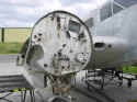 This next sequence shows the right firewall area. This shot is the before
picture. Note the damage to the bottom of the firewall. I have seen this on
several aircraft and is a result of removing the engines when the airframe was
going to be scrapped.
This next sequence shows the right firewall area. This shot is the before
picture. Note the damage to the bottom of the firewall. I have seen this on
several aircraft and is a result of removing the engines when the airframe was
going to be scrapped.
 Removing the firewall is essential to gain access to the forward truss and
nacelle area. It makes it a whole lot easier to clean the structure and inspect
the truss for cracks and abrasion damage. We found a crack in the second wing
rib (on both sides of the aircraft) that wouldn't have been visible without the
removal of the firewall. There is evidence of a gear up landing and some hard
landings on this airframe. Hard landings and ground loops can crack spars and
put stresses on the airframe that result in cracking and deformation. There are
several areas in the Beech 18 that are good indicators for such overstress. It
is very important to inspect your airframe for these indicators. I learned about
this the hard way as I had a spar break in my SNB-1 (Navy AT-11). Another
noteworthy item is the leading edge skin between the fuselage and the nacelle.
In this light you can see that the skin is very rough because of the hundreds of
times that the line service guys were banging the fuel hose around and putting
too much weight on the thin skins. This is typical of Twin Beech's that have
seen a lot of commercial use. These skins and many others with similar damage
will be replaced.
Removing the firewall is essential to gain access to the forward truss and
nacelle area. It makes it a whole lot easier to clean the structure and inspect
the truss for cracks and abrasion damage. We found a crack in the second wing
rib (on both sides of the aircraft) that wouldn't have been visible without the
removal of the firewall. There is evidence of a gear up landing and some hard
landings on this airframe. Hard landings and ground loops can crack spars and
put stresses on the airframe that result in cracking and deformation. There are
several areas in the Beech 18 that are good indicators for such overstress. It
is very important to inspect your airframe for these indicators. I learned about
this the hard way as I had a spar break in my SNB-1 (Navy AT-11). Another
noteworthy item is the leading edge skin between the fuselage and the nacelle.
In this light you can see that the skin is very rough because of the hundreds of
times that the line service guys were banging the fuel hose around and putting
too much weight on the thin skins. This is typical of Twin Beech's that have
seen a lot of commercial use. These skins and many others with similar damage
will be replaced.
 Here the structure is being cleaned and is getting ready for primer.
 The steel truss has been given a coat of the special primer and the surrounding
aluminum structure has been painted with a light coat of zinc chromate
AN-TT-P-656.
The steel truss has been given a coat of the special primer and the surrounding
aluminum structure has been painted with a light coat of zinc chromate
AN-TT-P-656.
 The final coat of paint is aluminum pigmented paint just as they used at the
Beechcraft factory. Now it is off to the other side.
The final coat of paint is aluminum pigmented paint just as they used at the
Beechcraft factory. Now it is off to the other side.
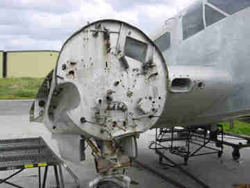
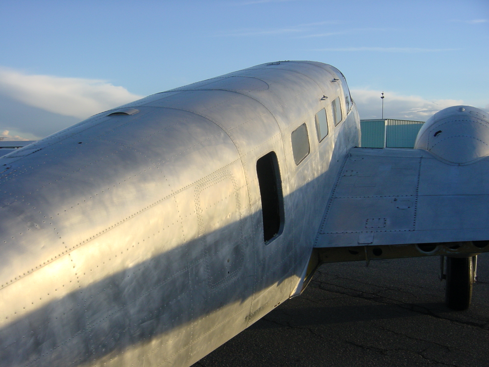
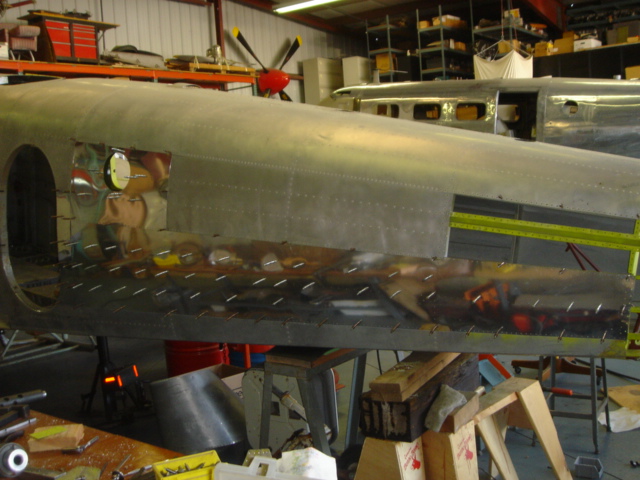
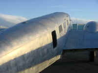
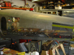
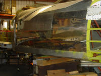
 The side skins of the nose have considerable damage from ice slinging off of the
propellers in flight. This old girl has seen some hard IFR in her day. Imagine
what it must have sounded like to the pilot and his passengers when a big chunk
of ice smacked into the side of the aircraft especially if it came off of one
blade at a time. The banging noise and the subsequent vibration must have been a
real thrill. Some of the dents are better than a half an inch deep and several
inched around.
The side skins of the nose have considerable damage from ice slinging off of the
propellers in flight. This old girl has seen some hard IFR in her day. Imagine
what it must have sounded like to the pilot and his passengers when a big chunk
of ice smacked into the side of the aircraft especially if it came off of one
blade at a time. The banging noise and the subsequent vibration must have been a
real thrill. Some of the dents are better than a half an inch deep and several
inched around.
The nose of any aircraft is the focal point and this is
especially true of the AT-11. The owners wanted the dents removed and they
wanted the nose to look just as it did when she came from the factory.
 The first order of business is to remove the damaged skins. This also gives
great access to the hard to reach areas under the cockpit floor structure.
The first order of business is to remove the damaged skins. This also gives
great access to the hard to reach areas under the cockpit floor structure.
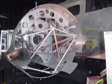
 Here you can see the bombardiers nose hatch opened for the first time in 50
years. This hatch , which was primarily used to install and remove the bomb
sight, had been riveted shut on one side and had many holes augured into it for
antennas and who knows what. One antenna was placed on the door hinge line and a
1 inch hole was bored right through the door frame. The cad plated locking pins
were solidly rusted onto their sockets and even though they were soaked in mouse
milk for several months prior, they wouldn't budge. One interesting aspect of
this hatch was how it was a closed structure that used one of the first blind
fasteners; the explosive rivet. Beech made extensive use of the explosive rivet
in these early aircraft. The explosive rivet had a small charge within the shank
that, when heated with a riveting iron, would fire off the charge which would
expand the shank of the rivet. I have shot off a few of these rivets and they
really go off with a bang.
Here you can see the bombardiers nose hatch opened for the first time in 50
years. This hatch , which was primarily used to install and remove the bomb
sight, had been riveted shut on one side and had many holes augured into it for
antennas and who knows what. One antenna was placed on the door hinge line and a
1 inch hole was bored right through the door frame. The cad plated locking pins
were solidly rusted onto their sockets and even though they were soaked in mouse
milk for several months prior, they wouldn't budge. One interesting aspect of
this hatch was how it was a closed structure that used one of the first blind
fasteners; the explosive rivet. Beech made extensive use of the explosive rivet
in these early aircraft. The explosive rivet had a small charge within the shank
that, when heated with a riveting iron, would fire off the charge which would
expand the shank of the rivet. I have shot off a few of these rivets and they
really go off with a bang.
I have several customers who have expressed an interest in
having a glass nose installed on their Twin Beech. As a result we have begun
tooling up to reproduce the complete AT-11 nose structure that can replace and
standard Twin Beech metal nose. We can even replace the nose on the Super 18's.
There are several AT-11 still flying that have had the glass nose replaced with
a metal nose. Soon these AT-11's will be able to have their nose structures
restored back to their original configuration.
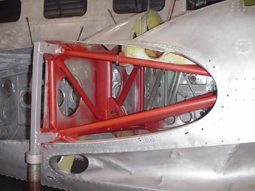
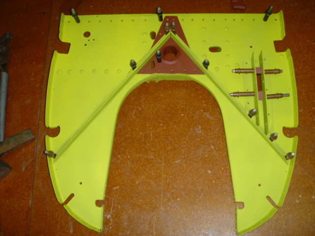
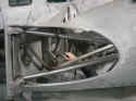
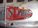
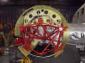
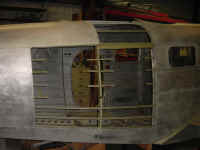
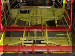 Here is the floor structure of the cockpit after having been cleaned and primed.
The red area is the special conversion coating that we use on ferrous or steel
structures. The red area in the lower part of the picture is the top elliptical
tube of the spar structure. This beam also supported the entry to the cockpit.
Here is the floor structure of the cockpit after having been cleaned and primed.
The red area is the special conversion coating that we use on ferrous or steel
structures. The red area in the lower part of the picture is the top elliptical
tube of the spar structure. This beam also supported the entry to the cockpit.
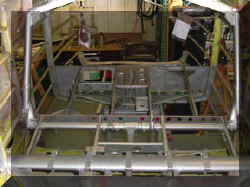 This is the same structure after it has been given its final coat of paint. One
interesting thing is that the co pilots control column can be disengaged from
the pilots side. This was to allow the student and instructor to gain access to
the nose. This is peculiar to the AT-11 only.
This is the same structure after it has been given its final coat of paint. One
interesting thing is that the co pilots control column can be disengaged from
the pilots side. This was to allow the student and instructor to gain access to
the nose. This is peculiar to the AT-11 only.
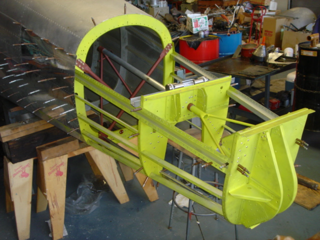
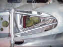
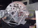
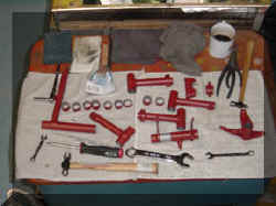 There are quite a few parts to the rudder cross shaft assembly. This is the
structure that supports the pilots and co pilots rudder pedals and the pilots
brakes. The co pilot didn't have brakes in this or any of the early Beech 18's
and the rudder pedals on the right side could be removed and stowed on the side
wall. This, like the swing away control column, was also used to ease access to
the nose. Can you pick out the mechanics most important tool in this picture? I
will give you a hint; it is in the white cup in the upper right corner of the
photo.
There are quite a few parts to the rudder cross shaft assembly. This is the
structure that supports the pilots and co pilots rudder pedals and the pilots
brakes. The co pilot didn't have brakes in this or any of the early Beech 18's
and the rudder pedals on the right side could be removed and stowed on the side
wall. This, like the swing away control column, was also used to ease access to
the nose. Can you pick out the mechanics most important tool in this picture? I
will give you a hint; it is in the white cup in the upper right corner of the
photo.
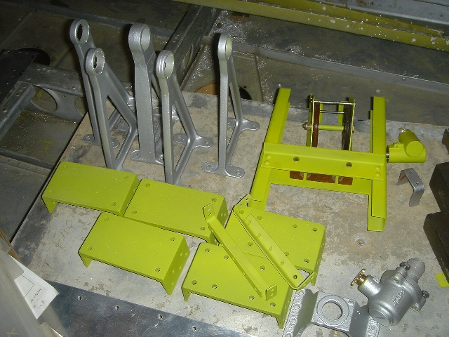
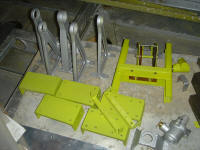
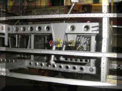 Here are all of the parts above, with their final paint, installed in the
cockpit floor structure. It will last at least another 50 years!
Here are all of the parts above, with their final paint, installed in the
cockpit floor structure. It will last at least another 50 years!
 Considering where we started...
 she has come along way.
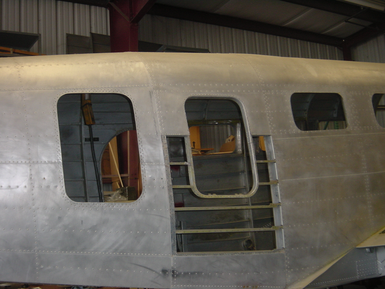
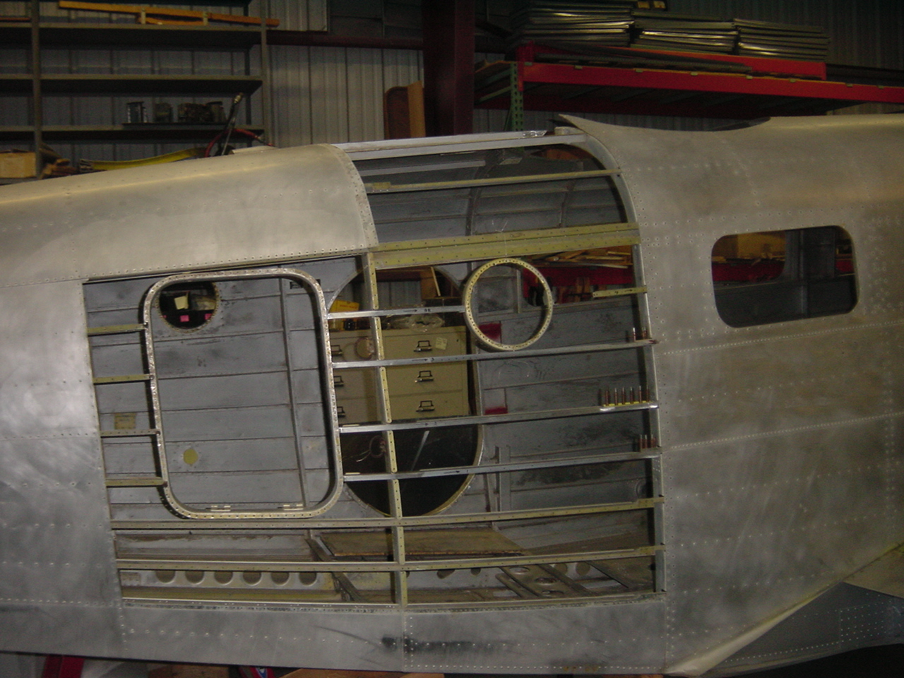
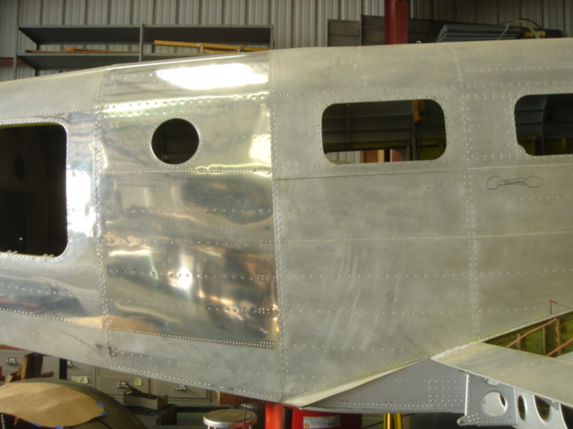
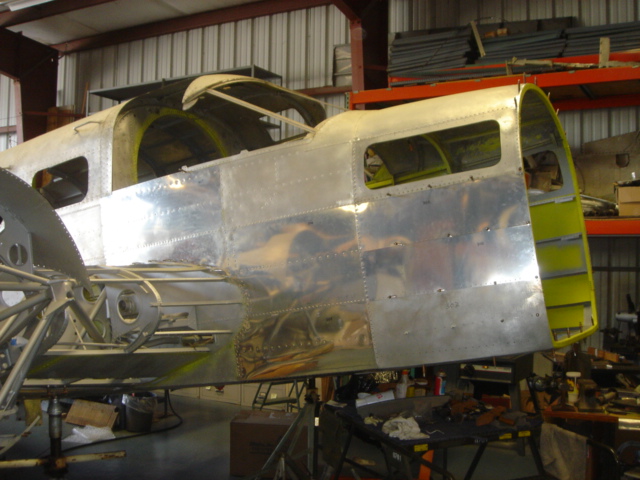
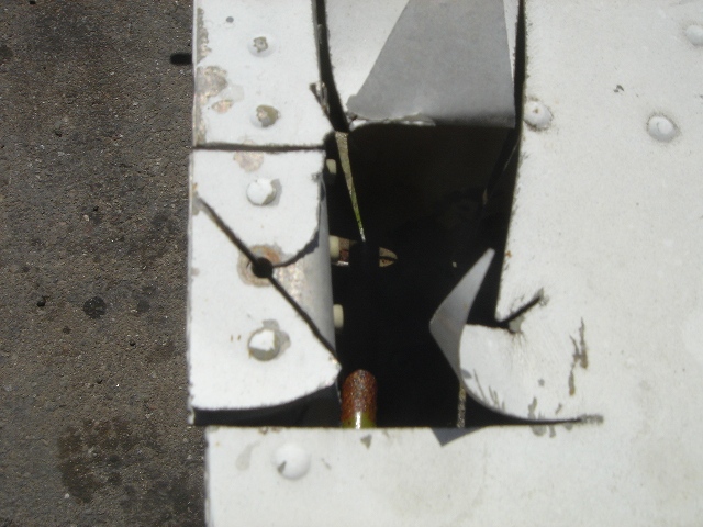
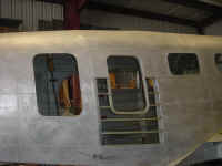
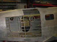
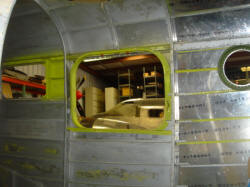
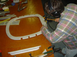
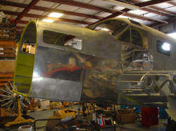
 The original gunners escape hatch was moved forward one frame bay and was turned
into a baggage door/escape hatch. We decided to move the hatch back to its
original location (you can see the original rivet pattern in the expanded photo)
and replace the original port hole. The owner, in the interest of safety, would
like the standard escape hatch put in the right side in the normal
location.
The original gunners escape hatch was moved forward one frame bay and was turned
into a baggage door/escape hatch. We decided to move the hatch back to its
original location (you can see the original rivet pattern in the expanded photo)
and replace the original port hole. The owner, in the interest of safety, would
like the standard escape hatch put in the right side in the normal
location.
First we shored up the airframe
with a tail stand and a beam supporting the fuselage under the trailing edge.
This is important because as you remove skins the structure becomes more
flexible and weak. We want support it to make certain that we do not introduce a
twist or screw up the airframe alignment.
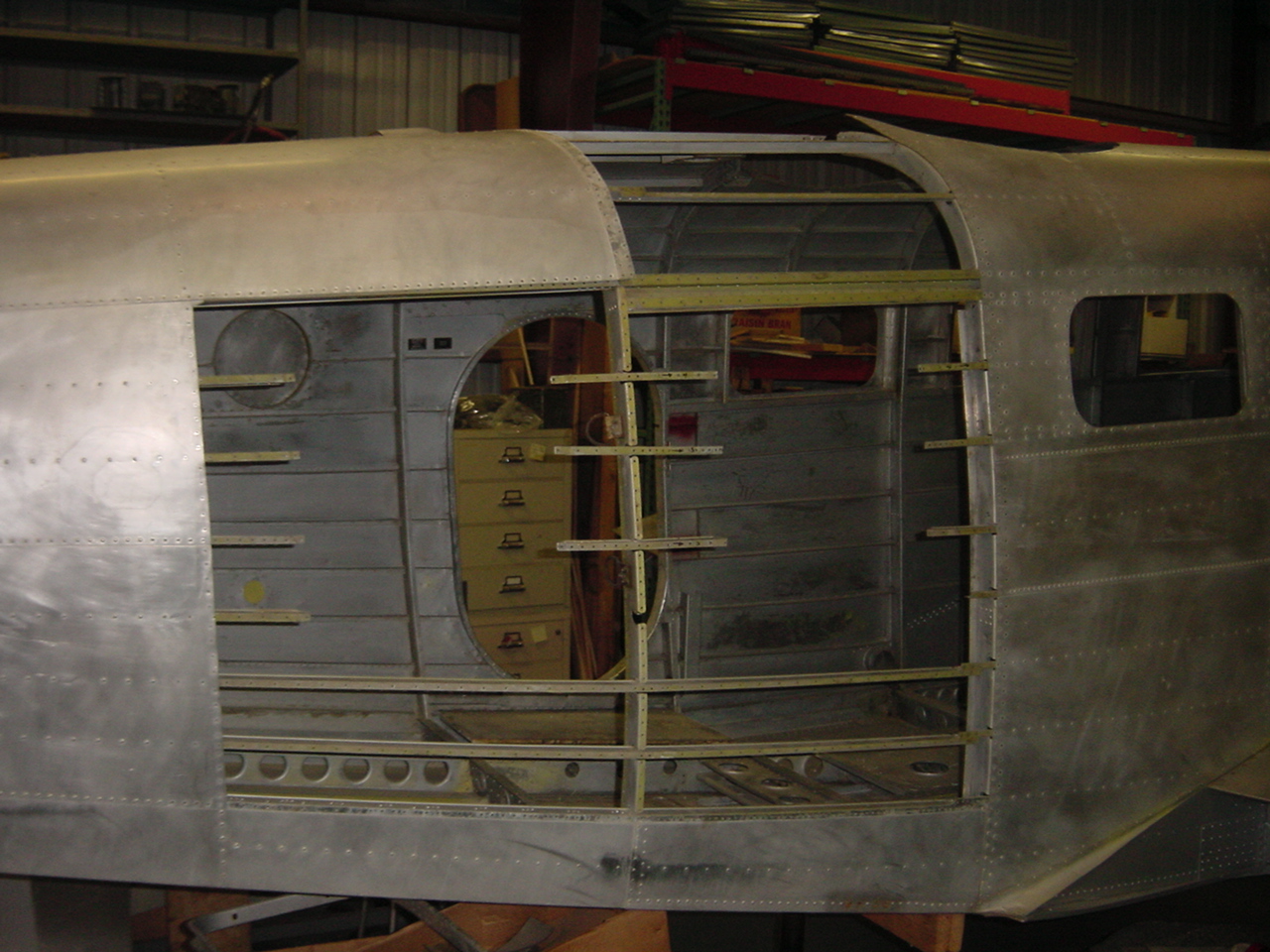
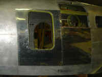
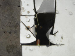
 Here the plug has been removed from the skinned over
original hatch location and the hatch frame is being removed so it can go back
to where it belongs.
Here the plug has been removed from the skinned over
original hatch location and the hatch frame is being removed so it can go back
to where it belongs.
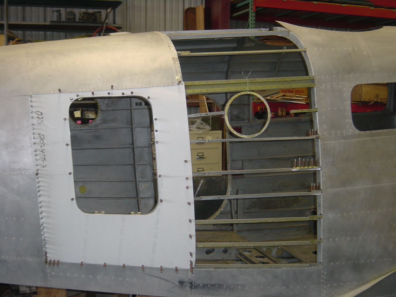
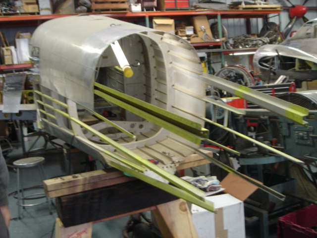
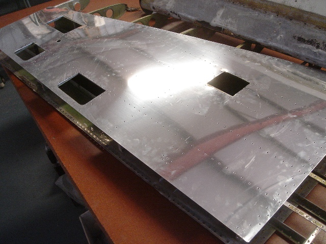
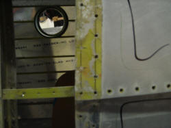
 The skins have been removed so the underlying
structure can be restored to the original configuration. What I find interesting
is that when you remove the skins you can see the pencil marks showing that the
rivet patterns were laid out by hand at the Beech factory.
The skins have been removed so the underlying
structure can be restored to the original configuration. What I find interesting
is that when you remove the skins you can see the pencil marks showing that the
rivet patterns were laid out by hand at the Beech factory.
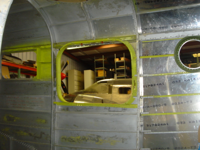
 Here the frame for the hatch and the port hole are back where they belong.
 The skins are being fitted, trimmed and are Clecoed into place.
 Once the skins are fitted...
 The riveting begins
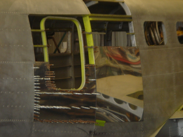
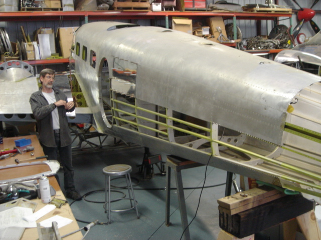
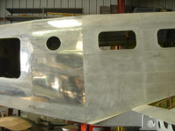 With the riveting done our attention turned to the customers
wishes for a standard escape hatch. The normal position for the escape hatch on
a Beech 18 is where the rectangular window is just forward of the port hole.
With the riveting done our attention turned to the customers
wishes for a standard escape hatch. The normal position for the escape hatch on
a Beech 18 is where the rectangular window is just forward of the port hole.
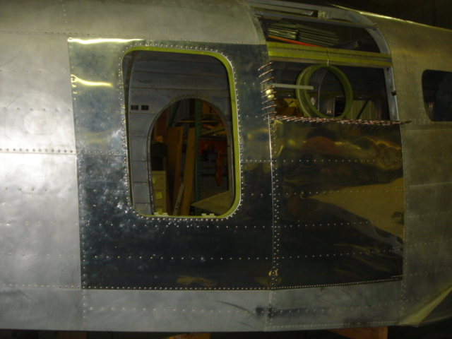
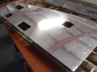
 Because of the excessive number of extra holes left after the rectangular window
was removed, a new skin was fabricated prior to the installation of the hatch
frame.
Because of the excessive number of extra holes left after the rectangular window
was removed, a new skin was fabricated prior to the installation of the hatch
frame.
 The frame was positioned in the standard location and the stringers were
fabricated to fit.
The frame was positioned in the standard location and the stringers were
fabricated to fit.
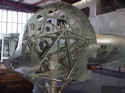
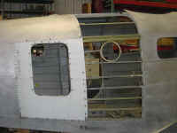
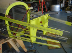
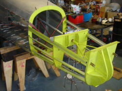
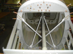
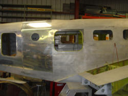 Here is the finished frame and right side of the aircraft. The only thing to
keep this from being closed out is the manufacture of the turret ring and its
installation on the top of the same bay.
Here is the finished frame and right side of the aircraft. The only thing to
keep this from being closed out is the manufacture of the turret ring and its
installation on the top of the same bay.
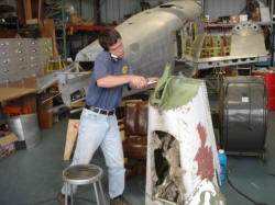
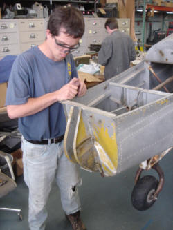 This is Steven the latest member of our team here at Vintage Aircraft. He is one
sharp mechanic and we are very fortunate to have him. Steven has begun the
repair to the tail area. The tail came with major damage that I believe was
caused by forklifts moving the airframe around the various storage yards. It
looks like the tail was dropped several times. In this shot you can see the
buckled rear bulkhead. The lower longerons are also buckled along with the
bulkhead forward of the tail gear.
This is Steven the latest member of our team here at Vintage Aircraft. He is one
sharp mechanic and we are very fortunate to have him. Steven has begun the
repair to the tail area. The tail came with major damage that I believe was
caused by forklifts moving the airframe around the various storage yards. It
looks like the tail was dropped several times. In this shot you can see the
buckled rear bulkhead. The lower longerons are also buckled along with the
bulkhead forward of the tail gear.
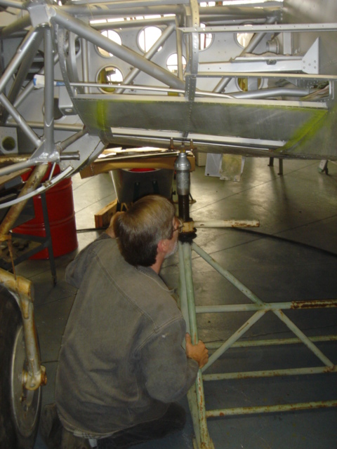
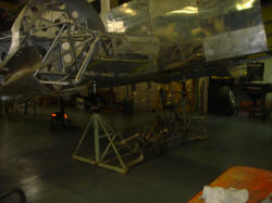
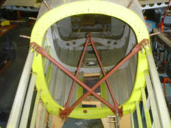
 Before we begin disassembling the tail we stabilize the airframe on the fixed
jack. Then the airframe is leveled and the fuselage is supported in several
locations. This is critical to maintain the alignment of the tail to the
fuselage and wings. When you start removing skins, the airframe becomes quite
flimsy and it is easy to rivet a twist into the airframe. We have mounted
several precision levels to the airframe to make sure that we maintain the
alignment. Here Ricky is jacking and leveling the AT-11.
Before we begin disassembling the tail we stabilize the airframe on the fixed
jack. Then the airframe is leveled and the fuselage is supported in several
locations. This is critical to maintain the alignment of the tail to the
fuselage and wings. When you start removing skins, the airframe becomes quite
flimsy and it is easy to rivet a twist into the airframe. We have mounted
several precision levels to the airframe to make sure that we maintain the
alignment. Here Ricky is jacking and leveling the AT-11.
 With the airframe stable and solid we can begin to remove the skins.
 The disassembly begins by drilling off the damaged skins.
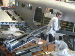
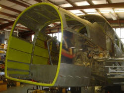
 While Steven is working on the tail, Ricky starts on the left side of the
fuselage. The skin that was removed had several dents and patches so the owner
wanted it replaced. Inside the fuselage you can see the curved lower bulkhead
which was the original location of the tunnel gun. Not to many people know that
the AT-11 had a tunnel gunner that manned a flexible 30 caliber AN M-2 Browning
machine gun. The tunnel gun position on this particular AT-11 was skinned over
when it was civilianized after WWII. In this shot you can see that the fuselage
is supported at three bulkheads aft of the trailing edge.
While Steven is working on the tail, Ricky starts on the left side of the
fuselage. The skin that was removed had several dents and patches so the owner
wanted it replaced. Inside the fuselage you can see the curved lower bulkhead
which was the original location of the tunnel gun. Not to many people know that
the AT-11 had a tunnel gunner that manned a flexible 30 caliber AN M-2 Browning
machine gun. The tunnel gun position on this particular AT-11 was skinned over
when it was civilianized after WWII. In this shot you can see that the fuselage
is supported at three bulkheads aft of the trailing edge.
 Back to the tail where Steven is really going to town. All three bulkheads
(number 13, 14, 15) were damaged.
Back to the tail where Steven is really going to town. All three bulkheads
(number 13, 14, 15) were damaged.
 Bulkhead number 15, the one severely buckled in the photo 6 pictures above, was
not repairable so we removed one from a cut off tail section that I picked up in
a scrap yard. Here Steven is beginning to remove bulkhead number 15 from the
scrap tail. The problem that you run into is that these aircraft were built by
hand and so the holes drilled in the skin were laid out by hand and as a result
the rivet holes will not line up.
Bulkhead number 15, the one severely buckled in the photo 6 pictures above, was
not repairable so we removed one from a cut off tail section that I picked up in
a scrap yard. Here Steven is beginning to remove bulkhead number 15 from the
scrap tail. The problem that you run into is that these aircraft were built by
hand and so the holes drilled in the skin were laid out by hand and as a result
the rivet holes will not line up.
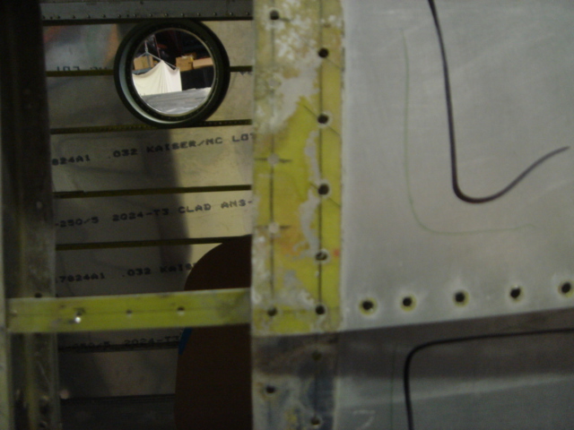
 Here is a good example. All throughout the airframe when you remove a skin you
will see the pencil marks from the factory workers where they marked the spots
for drilling the rivet holes. This makes it very hard to take a part from
another airframe as none of the holes will match. This wasn't a big issue for
using the used bulkhead number 15 from the scrap tail as most of the skins are
going to be replaced anyway.
Here is a good example. All throughout the airframe when you remove a skin you
will see the pencil marks from the factory workers where they marked the spots
for drilling the rivet holes. This makes it very hard to take a part from
another airframe as none of the holes will match. This wasn't a big issue for
using the used bulkhead number 15 from the scrap tail as most of the skins are
going to be replaced anyway.
 Here is bulkhead number 14 after Steven has straightened the damage lower
corners. He removed the steel welded mounting flange for the slide tube (shown
in red oxide primer) to be certain that the rust was removed properly. A doubler
to repair a crack will also be fabricated and riveted in place. Now the part
will last another 60 years.
Here is bulkhead number 14 after Steven has straightened the damage lower
corners. He removed the steel welded mounting flange for the slide tube (shown
in red oxide primer) to be certain that the rust was removed properly. A doubler
to repair a crack will also be fabricated and riveted in place. Now the part
will last another 60 years.
 Steven is straightening bulkhead number 13 as the lower portion was also
damaged.
Steven is straightening bulkhead number 13 as the lower portion was also
damaged.
 Here both of the repaired bulkheads have been primed and fitted. The lower longerons on each side of the tail gear well were damaged and new
parts were fabricated and are being fitted here.
Here both of the repaired bulkheads have been primed and fitted. The lower longerons on each side of the tail gear well were damaged and new
parts were fabricated and are being fitted here.
 Here the repaired bulkheads are being fitted along with the repaired and primed
cross brace.
Here the repaired bulkheads are being fitted along with the repaired and primed
cross brace.
 The new slide tube and the attaching Y strut are being fitted.
 After fitting the parts they are removed for finish paint. This area was painted
with aluminum pigmented paint to match the original factory finish. The new tail
gear truss and fork have been fitted and temporarily installed.
After fitting the parts they are removed for finish paint. This area was painted
with aluminum pigmented paint to match the original factory finish. The new tail
gear truss and fork have been fitted and temporarily installed.
 As good as new!
 Work progresses on the left side of the fuselage. Sometimes we need to resort to
creative methods to keep our workers motivated. Here we see Ricky working under
the gun...or guns. If you need your B-17 tail turret built up complete with twin
50's just give us a call. We love working on WWII armament, it is one of our
many specialties.
Work progresses on the left side of the fuselage. Sometimes we need to resort to
creative methods to keep our workers motivated. Here we see Ricky working under
the gun...or guns. If you need your B-17 tail turret built up complete with twin
50's just give us a call. We love working on WWII armament, it is one of our
many specialties.
 Here the skins are being fitted for the left side of the aft fuselage.
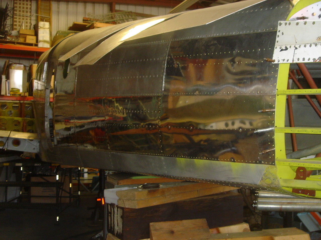
 Work continues on skinning the nose and repairing the ice damage to each side.
In heavy icing the chunks of ice will sling off the prop and hit the side of the
fuselage with a bang. I imagine that this would grab your attention in a hurry!
Work continues on skinning the nose and repairing the ice damage to each side.
In heavy icing the chunks of ice will sling off the prop and hit the side of the
fuselage with a bang. I imagine that this would grab your attention in a hurry!
 The attach angles for the horizontal stabilizer are drilled differently for C
model and D model aircraft. This AT-11 didn't come with its original horizontal
but it came with one that was cut off of another Beech complete with a tail
cone. The attach angles that match the horizontal are being fitted in this
photo. The owner has decided to use the intermediate angle of incidence change
on his AT-11. Beech's had three different angle of incidence on the horizontal.
Over time it was decided to raise the front of the horizontal stabilizer in
order to gain more speed. The WWII era or C model aircraft had the lowest angle
of incidence which made for lower stall speeds and better short field
performance. The problem was that in cruise the elevator was not streamlined
with the horizontal stabilizer thus creating more drag and reducing the cruise
speed. Beech raised the angle of incidence to what I call the middle or
intermediate position on the D model aircraft. Another mod was done on later
aircraft to raise the front of the stabilizer even further. This did raise the
stall speed and consequently the landing roll but this wasn't as important as
the increase in cruise speed. Beech made a kit for this modification so it is a
simple process as far as the paperwork is concerned.
The attach angles for the horizontal stabilizer are drilled differently for C
model and D model aircraft. This AT-11 didn't come with its original horizontal
but it came with one that was cut off of another Beech complete with a tail
cone. The attach angles that match the horizontal are being fitted in this
photo. The owner has decided to use the intermediate angle of incidence change
on his AT-11. Beech's had three different angle of incidence on the horizontal.
Over time it was decided to raise the front of the horizontal stabilizer in
order to gain more speed. The WWII era or C model aircraft had the lowest angle
of incidence which made for lower stall speeds and better short field
performance. The problem was that in cruise the elevator was not streamlined
with the horizontal stabilizer thus creating more drag and reducing the cruise
speed. Beech raised the angle of incidence to what I call the middle or
intermediate position on the D model aircraft. Another mod was done on later
aircraft to raise the front of the stabilizer even further. This did raise the
stall speed and consequently the landing roll but this wasn't as important as
the increase in cruise speed. Beech made a kit for this modification so it is a
simple process as far as the paperwork is concerned.
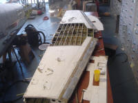
In fitting the attach angles we need to install the horizontal to be certain
that it is aligned perfectly with the fuselage and wings. We began work on the
horizontal which was not in the best of shape.
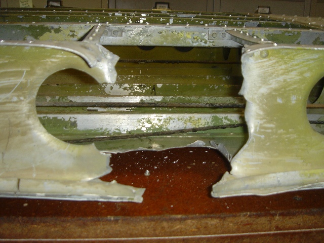
 This horizontal was still attached to the last three feet of the fuselage. This
was a bonus as it provided parts to repair the bent aft fuselage. Someone
attacked this horizontal with a saw for no obvious reason.
This horizontal was still attached to the last three feet of the fuselage. This
was a bonus as it provided parts to repair the bent aft fuselage. Someone
attacked this horizontal with a saw for no obvious reason.
 The holes and cuts don't seem top make sense as there wasn't anything inside to
gain access to.
The holes and cuts don't seem top make sense as there wasn't anything inside to
gain access to.
 The rear spar was sawed in several places.
 With all of this damage we explored replacing the horizontal with another one.
All of the ones we found had other damage like hail, corrosion or dents in
the leading edge requiring re skinning. It was decided that repairing the
original horizontal was more economically feasible that buying a new one and
having to rebuild it.
With all of this damage we explored replacing the horizontal with another one.
All of the ones we found had other damage like hail, corrosion or dents in
the leading edge requiring re skinning. It was decided that repairing the
original horizontal was more economically feasible that buying a new one and
having to rebuild it.
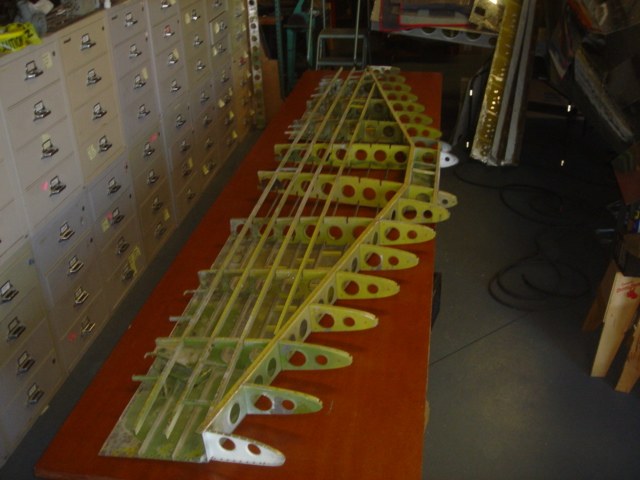
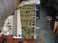
 The skins were removed and the repairs to the structure began.
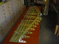
 The individual components of the horizontal are cleaned, primed and painted
 New skins are made.
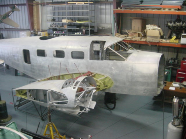
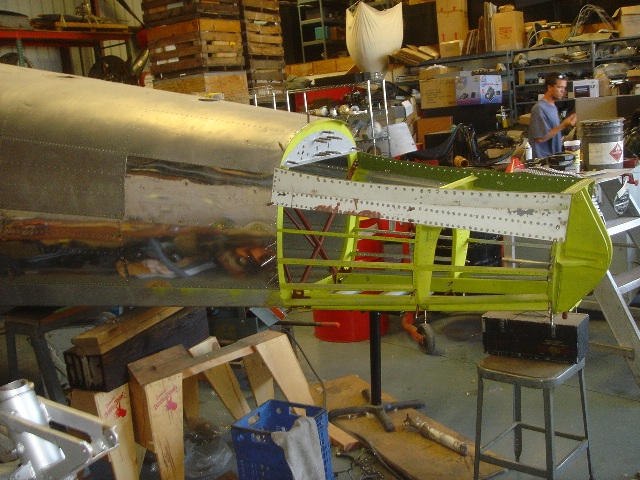
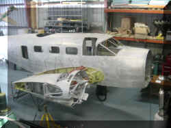
 On the other end of the AT-11 a new firewall is being fitted.
Stay tuned for more photos as the progress continues.
ALL OF THE IMAGES ARE THUMBNAILS SO JUST
CLICK ON ONE TO SEE A LARGER PICTURE
TO ALL OF OUR
COUNTRY'S VETERANS, WE HERE AT VINTAGE AIRCRAFT WOULD LIKE TO SAY:
THANK YOU
FOR WHAT YOU DID FOR OUR COUNTRY!
HOME
PAGE VINTAGE AIRCRAFT
ANNOUNCEMENTS JOB
OPPORTUNITIES WARBIRD-RIDES AIRCRAFT
FOR SALE HOW THIS BEECH 18 MADNESS BEGAN THINKING
ABOUT A TWIN BEECH PROJECT? BEECH
18 SPAR CONCERNS BEECH 18
SPAR STRAP KITS BEECH
18 GROUND TRANSPORTATION TWIN BEECH
PHOTOS BEECHCRAFT RC-45J BEECH AT-11 KANSAN
RESTORATION OF AT-11 41-27603
C-45H N314WN TECHNICAL
MANUALS AND PUBLICATIONS STOCKTON
FIELD AVIATION MUSEUM WWII
WARBIRD GROUP NORDEN
BOMB SIGHT WWII RADIO PAGE
AIR
SHOWS AND EVENTS VOLUNTEERS
WAR STORIES
B-25 OLD GLORY
B-29 IT'S HAWG WILD
B-29 42-65401 NOSE SECTION
B-29 GUNNERY SYSTEM
SEARCH THIS WEB SITE CONTACT
US
VINTAGE AIRCRAFT
7432 C.E. DIXON STREET
STOCKTON, CALIFORNIA USA 95206
(209) 982 0273
(209) 982 4832 FAX
taigh@twinbeech.com
KEEP
'EM FLYING...FOR HISTORY!

 The first step is to bring the project home. Not a simple task with a Twin
Beech. This is the AT-11 when she arrived in Stockton. This is our trailer that
we built especially for transporting Twin Beech airframes. For more information
about moving the Twin Beech click here.
The first step is to bring the project home. Not a simple task with a Twin
Beech. This is the AT-11 when she arrived in Stockton. This is our trailer that
we built especially for transporting Twin Beech airframes. For more information
about moving the Twin Beech click here.