Differences and Modifications
This page covers some of the various configurations of the Beech 18
If you're viewing this page on your phone, make sure to view it in landscape mode for the best results. Thank you!

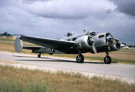
It has been our experience that no two Twin Beech's are alike, especially these days, as each aircraft will have its own set of modifications. Some of these are shown below.
All of the images on this page are thumbnails. Just click on a picture to see a larger photo.
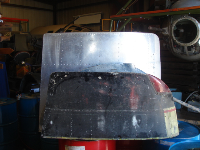
 Round Tip
This is the stock factory round wing tips found on all the C (1945 and earlier) and D (1946 and later) model aircraft.
 Square Tip
This is the squared wing tip typical of the E, G and H aircraft. This was a Beech factory tip that helped increase the gross weight as well as improving
the low speed and stall characteristics. The Beech squared tip has wash out which reduces the angle of attack of the wing tip thus the tip will stall last
giving good aileron authority and control late into the stall. This will reduce the wing break tendencies during the stall and will tend to mush straight ahead instead of going hard over.
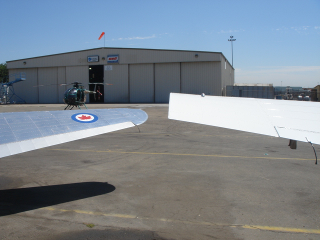 Comparison of Both
Here is a comparison shot showing the basic difference between the round and the big square tip.
 Aerospace Fiberglass Tip
This is one of the STC's wing tips that can be found on many Beech's. This particular one is an Aerospace wing tip made out of fiberglass.
These tips were typically a part of the gross weight increase kits that many aftermarket companies produced to upgrade the Beech 18.
 PacAero Tip
The tip in the foreground is a Pacific Airmotive or PacAero. It was also part of a gross weight increase mod. This tip was made from a round Beech tip that was squared off to increase the surface area. I have placed the PacAero tip against a Beech manufactured round tip and a square tip for comparison.
 Another Comparison
As you can see the square tip is a lot longer than the others. You can easily see the difference in the surface area. I wonder how much benefit was gained by the Aerospace and the PacAero tips as they don't seem to have that much more surface area than the conventional tip.
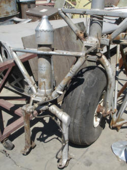
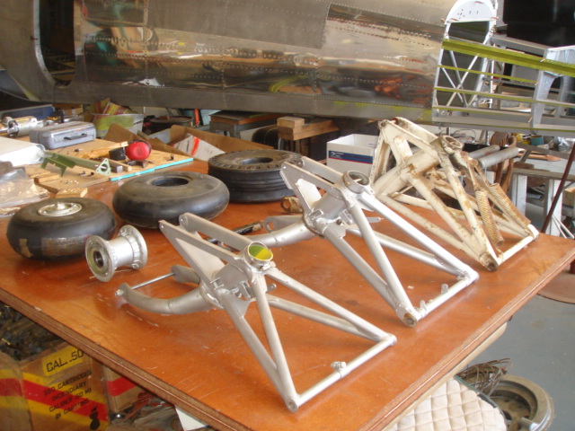
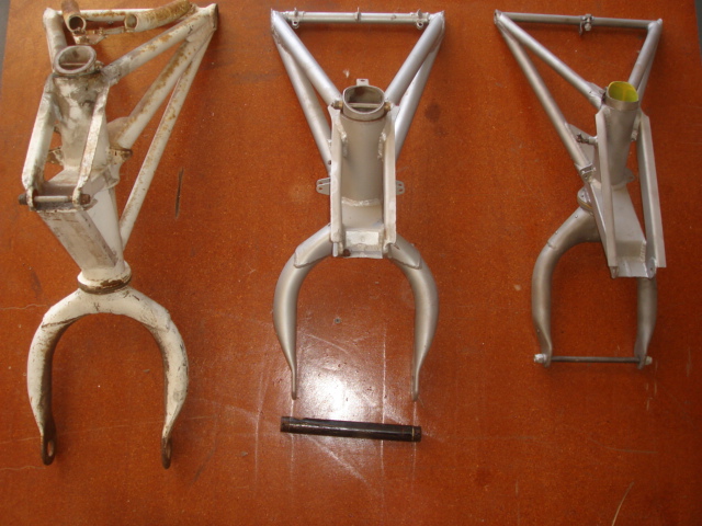
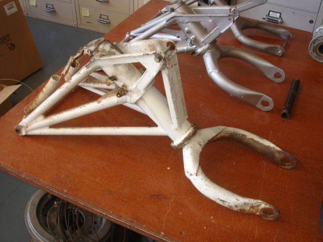
There are several different landing gear that can be found on the Beech. Mostly the landing gear can be identified by the lower fork of the gear leg as this is the part that is most visible.
The early aircraft (pre 1945) had a gear in which the lower fork was made up of welded tubing. This lower fork was angled and is commonly referred to as the dog house gear as the shape resembles a dog house.
This is Ray Plotes beautifully restored AT-11 that is the most stock AT-11 flying today. Although they are running Cleveland wheels and brakes they have kept the original dog house gear. In this shot you can see the angle of the welded gear leg.
There were two types of the dog house gear. One had shorter forks and was used with the real early (pre and early WWII) Goodyear multi disc brakes and the balloon tires or Airwheels. These aircraft also had shorter gear wells which necessitated modifying the aft end of the gear well if you wanted to change it to the 33SC or the 1100-12 wheels.
The dog house gear was designed for the early aircraft that had a 7850 pound gross weight. Incidentally the AT-11 bombardier trainer had a take off weight of 9800 pounds but a landing weight of 7850 since it would typically be dropping 1000 pounds of bombs. When the gross weight started to increase Beech came up with a stronger gear hence the wishbone gear.
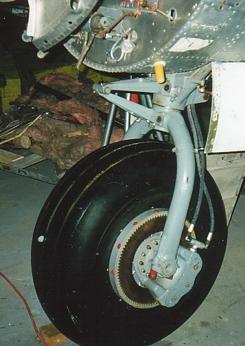
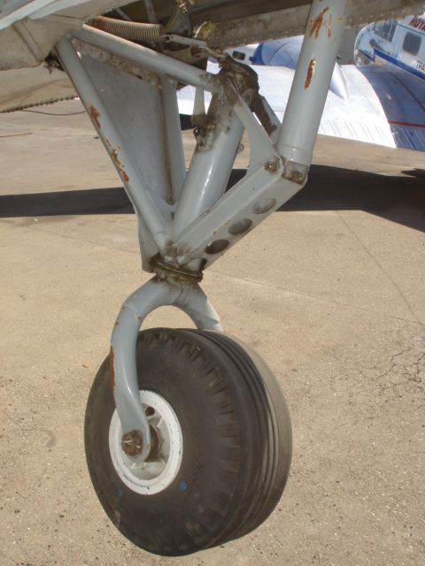
 Wishbone
This is the most common landing gear found on flying conventional gear Twin Beech's today. This lower gear fork is made up with a rounded one piece leg
that is commonly referred to as the wishbone landing gear.
 Wishone Collapsed
Here is an interesting comparison that shows the gear leg collapsed. Both the dog house and the wishbone gear have the same stroke. The upper
cylinders of both types of gear are also very different. Although no individual parts are interchangeable between the dog house and the wishbone gear, the airframe will accept either
gear as they are interchangeable by assembly.
 Comparison, Dog House and Wishbone
From the Beech boneyard comes this shot of the dog house and the wishbone gear next to each other.

 Tri Gear
Then there are the tricycle gear aircraft. This particular one is a Tradewinds conversion with the single tail. The vertical stabilizer is
made from a Twin Beech horizontal stabilizer turned on end, cut and fit to form the vertical. This gear is also known as the Volpar tri gear. This gear was a modification that
eventually was bought by Beech and was incorporated into the last Beech 18's built. The upper part of the main gear leg on the tricycle aircraft was made from the upper conventional
gear cylinder from the wishbone style gear. Both the nose and the main wheels run 8.50-10 wheels and a different model of Cleveland wheels and brakes.
 Modified Tri Gear
Here is a shot of the gear well of Remy's beautiful tri gear in Argentina. You can see the white painted upper gear leg and strut was made
from the conventional wishbone gear.
 H-18
H-18
Here is an H-18 conventional gear Beech belonging to Steve Oxman that has factory 8.50-10 wheels and the single fork gear leg. Below is a close up of the factory stock H model gear leg. There were some strength issues with this kind of gear and many have been replaced with the earlier full wishbone style of
landing gear.
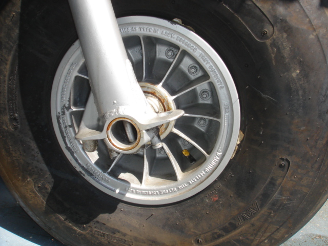
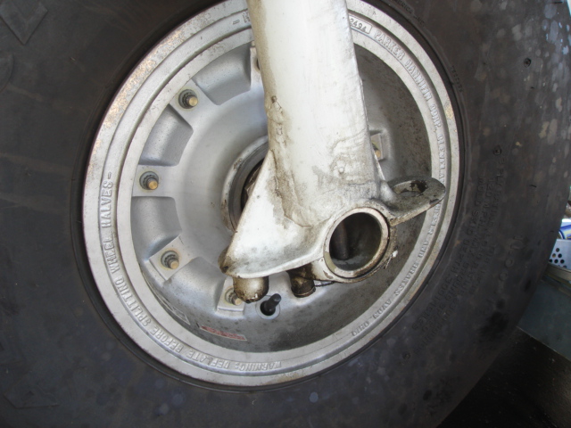
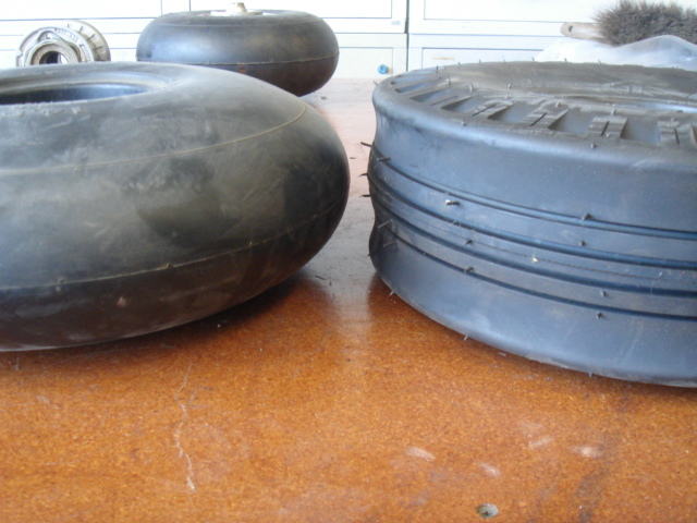
There are five different types of wheels and brakes found on the different Beech's. The earliest system was the Goodyear Airwheel (also referred to as the balloon tires) system that used a multiple disc brake pack assembly. Don't cinfuse the early Goodyear Airwheel with the more common Goodyear 1100-12 wheel with the single brake disc rotor.
These early Airwheels were typically used on pre war (WWII) aircraft and also the early c-45's, F-2's and the AT-7 Navigation trainer. The tires are nearly impossible to find these days and I have yet to see these wheels, tires and brakes on any aircraft presently flying . The only ones that survive are on static display aircraft in museums.
This is the 33 SC Bendix wheel typically installed on all WWII military Beech's and C model aircraft. This was a drum style brake just like the drum brakes in your car...older car that is...This shows the assy is practically identical to those found on automobiles.
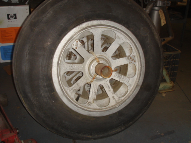
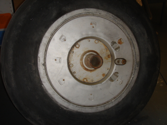
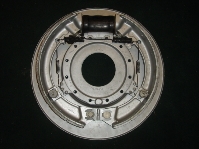
Note:This wheel is easily identified by the teardrop cutouts between the spokes. The 33SC wheels and tires are quite rare these days also because the tires and inner tubes are nearly impossible to find. They sure look good and there are several of us that want to get together to have a run of fresh tires made. The cost is substantial so the more people we have to help fund this the more cost effective it will be for us all. If you have a need for 33SC tires or tubes, contact me.
This is one of the few Beech's still running the original 33SC wheels and brakes. This beautiful UC-45E was built by the late Keith Cross and is now lovingly cared for by his Son Brian and his grandson Tyler. It is wonderful to know that Keith's efforts are going to live on through Brian and Tyler who are wonderful people. In fact Keith's whole family is great.
I have heard a lot of rumors about people complaining about the drum brakes. I learned to fly Beech's on these wheels and brakes and I think they are great. The tire and tube availability is certainly a big issue but as far as the braking ability they were always there when I needed them. I put on a new set of brakes when I built the aircraft and over 500 hours later they still had 50% pad left. I was operating out of a 2500 foot strip and the only time they ever faded was after I had pressure washed the aircraft and had water in the drums. Dragging the brakes out of the wash rack would cure this problem easily.
Braking capacity has always been an issue with the Beech and continues to this day. With gross weights increasing from 7850 on the C models up to 10,100 plus on the modified D's and later aircraft the braking capacity was increased.
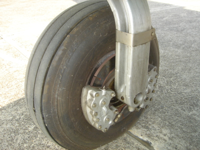
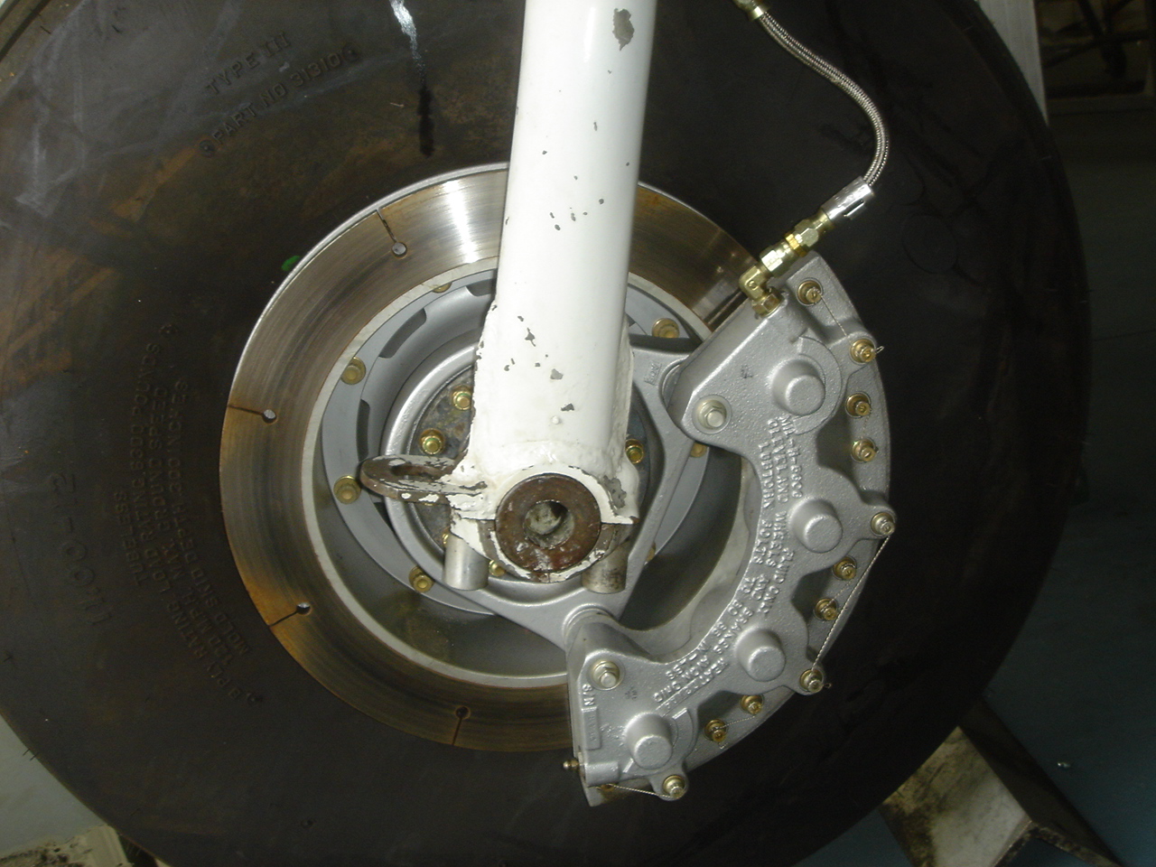
The next series of wheels and brakes was built by Goodyear and it used a single floating rotor or disc and 1100-12 wheels and tires. The disc came in two different types; one that was notched and one that had a gear cut to the outside diameter. The notched type soon fell out of favor to the gear type because of cracking issues. The gear type presented more surface area to distribute the braking energy from the rotor to the wheel.
 Goodyear Brakes
The Goodyear disc brake system is the most common brake in use on today's flying Beech's. It is easily identified by the web construction of the
wheels. Incidentally it is these webs and the bead flange where these wheels will crack. This should be a part of your pre flight as these wheels have seen a lot of cycles over the
years.
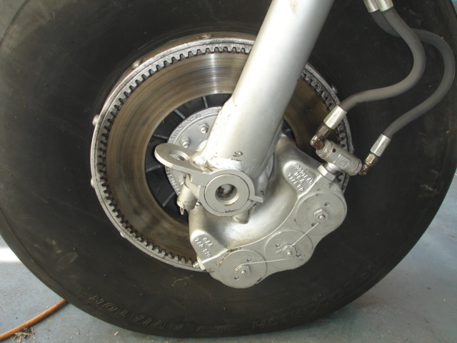 Goodyear Brake, Inboard
This view shows the more common gear type of rotor. You can see how the rotor meshes with a matching ring gear mounted in the wheel.
Look at the big screws that hold the ring gear into the wheel as I have seen these screws back out in operation. The Goodyear brake has three pistons built into the caliper that pinch
the floating rotor between six round brake pads or pucks.
There are two different styles of piston heads found on these calipers. The ones above has pins inside of adjusting nuts that indicate brake lining wear. The photos below has larger diameter tubes that will indicate brake lining wear. Here you can see the brake pucks and the gap is where the rotor or disc rides.
Note: I recommend the O ring along with the inner tube for added safety so if you get into a ground loop situation the air will not spill out of the tire should the bead become unset. If the bead of your tire is departing the wheel you will likely have much bigger problems going on at the time and a collapsing tire will certainly not help things!
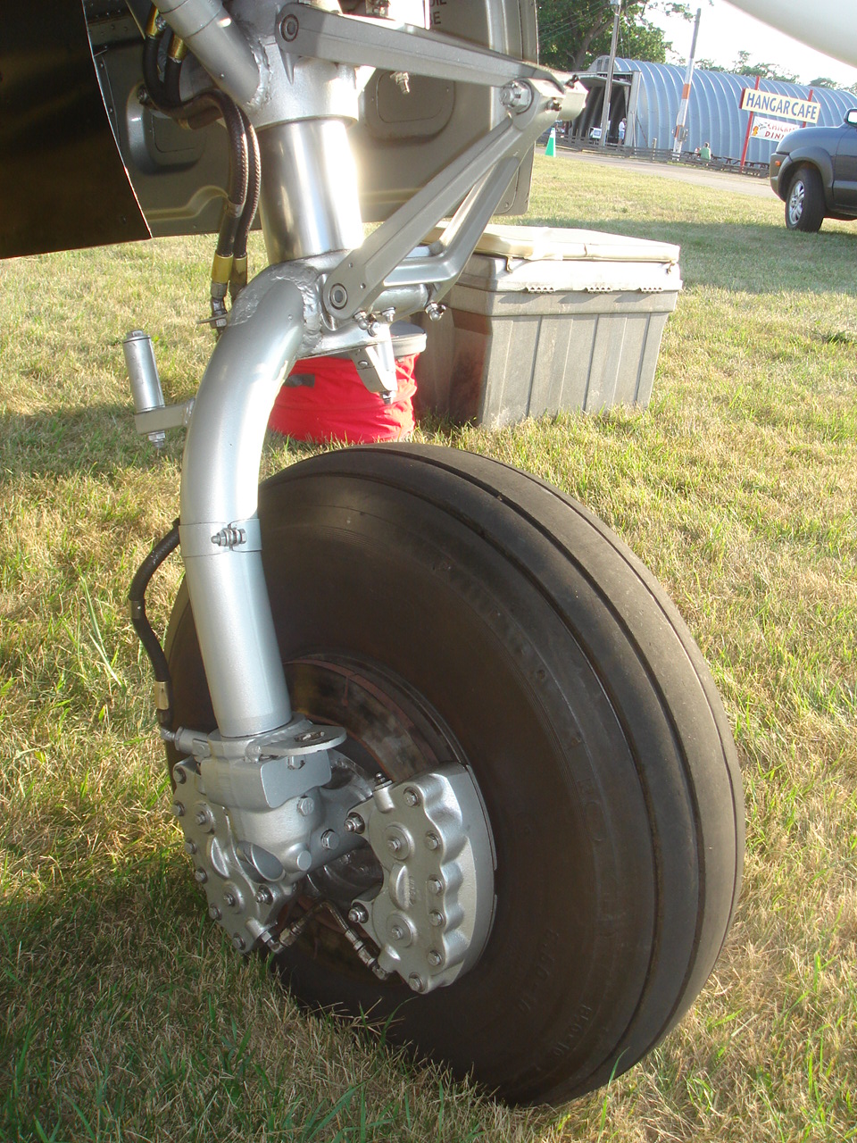
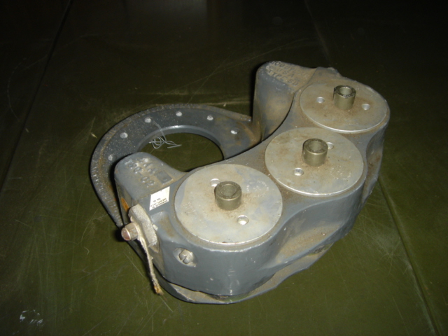
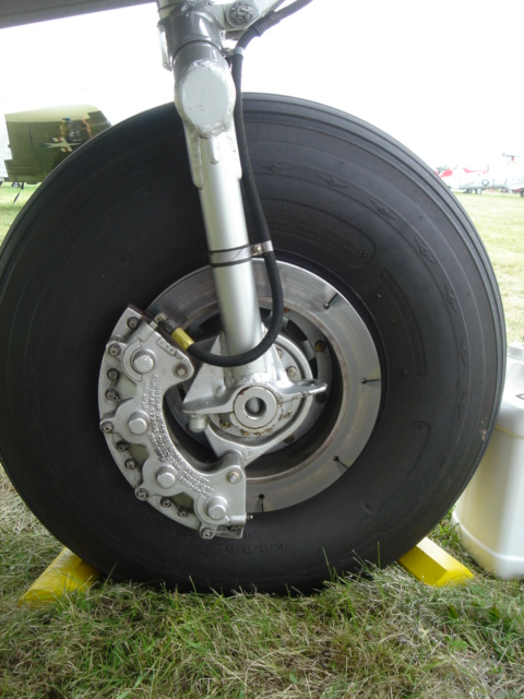
 Cleveland, Outboard
The latest wheel and brake is the Cleveland set. This is an STC'd system that does substantially increase the braking capacity. This wheel
is identified by the solid type of wheel without any significant flanges or spokes. This wheel can be used with or without an inner tube as long as there is an O ring installed between
the wheel halves.
 Cleveland, Inboard
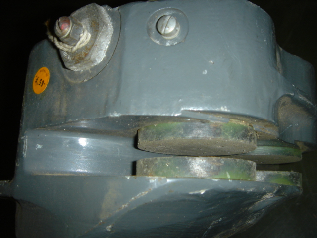
The Cleveland brake uses a fixed rotor and a floating (on two pins) caliper that has four pistons built into the housing. This brake has a
much larger brake pad, compared to the Goodyear brakes. Some people mention not being able to keep the aircraft from rolling when doing a run up with the Goodyear brakes.
I usually advise to try standing on top of the pedals to get the needed braking action. With the increased surface area of the Cleveland's this problem goes away.
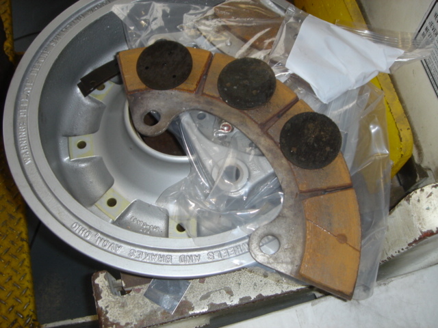 I took a set of Goodyear pucks and placed them on a Cleveland brake pad. It is easy to see the difference that exists between the two. This photo represents only one half of the
brake pads found on each wheel.
In my experience the Cleveland brakes seem to hold up well to the rigors of Twin Beech flight training. I have had many a student that will substitute lead feet for proper aircraft operation and technique.
After a season of air shows and heavy footed flight training I was amazed to see how well the Cleveland pads held up. There is something to say for the large increase in brake surface area.
I took a set of Goodyear pucks and placed them on a Cleveland brake pad. It is easy to see the difference that exists between the two. This photo represents only one half of the
brake pads found on each wheel.
In my experience the Cleveland brakes seem to hold up well to the rigors of Twin Beech flight training. I have had many a student that will substitute lead feet for proper aircraft operation and technique.
After a season of air shows and heavy footed flight training I was amazed to see how well the Cleveland pads held up. There is something to say for the large increase in brake surface area.
I still like the Goodyear system and I think that it is a very cost effective system.
 I have easily flown two seasons of flying rides (sometimes over 20 take offs and landings in a day, every weekend from April through October) before I have had to change the pucks. The Goodyear pucks
cost around $20 to $50 each and there are six per wheel. This is a lot cheaper that the Cleveland conversion kit that, last time I checked, was over $12,000. I think the Goodyear system is adequate
but the Cleveland kit is perfect for certain applications and pilots.
I have easily flown two seasons of flying rides (sometimes over 20 take offs and landings in a day, every weekend from April through October) before I have had to change the pucks. The Goodyear pucks
cost around $20 to $50 each and there are six per wheel. This is a lot cheaper that the Cleveland conversion kit that, last time I checked, was over $12,000. I think the Goodyear system is adequate
but the Cleveland kit is perfect for certain applications and pilots.
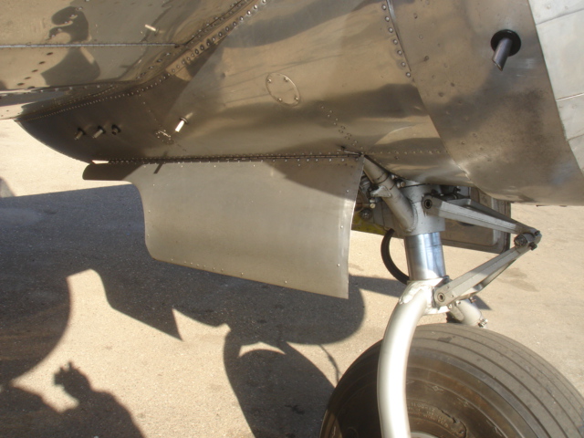
Here is a Set of Cleveland wheels and brakes modified to fit a C model landing gear, the dog house gear. The pins in the axel caps are different and some machining is required to adapt the Cleveland's to the old style gear. There is also a concern on tire clearance with the wing skin. The D model Beech's and latter have an additional fairing for this which is covered by the longer nacelle fairing.
There are three different angles of incidences on the horizontal stabs of the various models of the Twin Beech's that I have seen. The lowest angle of incidence can be found on unmodified C model aircraft (1945 and earlier). The second or what I call the middle one is typically found on factory D model and later aircraft. There is a third one or the highest angle of incidence which I believe is from an after market STC (Bob Parmerter or Nick can verify this).
 This photo to the right is the highest angle of incidence on a C-45H or D-18S. This is readily identifiable by the one piece fiberglass fairing and fillet. The top of the stabilizer is even with the top of the fuselage.
I learned to fly a Twin Beech in an unmodified SNB-1 (1943 Navy AT-11) that had the factory low angle on it. The low speed capabilities were wonderful which was great because I was flying out of a 2500 foot strip with dykes on each end (Palo Alto Airport in California). I would fly 90 knots on down wind, 80 on base and transition to 70 on final. I would roll in full back elevator trim and hit full flaps over the fence and pull the throttles back to idle she would float onto the runway almost hands off in the gentlest three point landing that you could imagine. I had never had such luck three pointing any other kind of tail wheel aircraft like that SNB-1 could. She would also slow down and stop very short without the need of much brake at all. She had the original 33SC tires and drum brakes. I would routinely get off on the first taxi way of that 2500 foot strip. I was delighted with her capabilities. When I installed the gun turret and fairings her stall characteristics were appreciable altered and the three point landing became a thing of the past.
In flight photos showed that, in normal cruise, the elevator of the SNB-1 was not streamlined with the horizontal stabilizer. It turns out that this was one of the problems that Beech wanted to rectify with the angle of incidence change. By raising the leading edge of the horizontal stab you can make the tail more streamlined and will reduce the drag thereby increasing the cruise speed. The angle change will also increase the speed at which the horizontal stab stalls thus increasing your overall stall speed and the touchdown speed/landing run. My impression was that as time went on cruise speed was more important that the short field characteristics which is why the change was adopted.
The next Beech that I flew regularly was an unmodified RC-45J (SNB-5P) which was basically a D model that was heavy with radios and other military gear. This Beech had the factory middle angle of incidence as most all D and later aircraft did. This aircraft was more critical on landing as you would tend to drop out of the sky in the three point attitude. Timing had to be right on the money unless you want to make the spar flex in ways that it wasn't meant to flex! You could still do it but the timing was critical.
I was selling rides in this Beech for a number of years so after a few months into the air show season of doing 15 to 20 flights a day I would start brushing up on the three points. I would usually pre-apologize to my passengers for the upcoming landing but it usually wasn't too bad. Once again the Beech would stop in an amazingly short distance when three pointed on. I would only try this when I was very current in the aircraft.
Most of the time a tail low wheel landing would suffice even for short strips. Speed is the critical thing for a short runway because any extra speed sure shows up in the landing roll. I would almost say that every extra knot will give you 100 more feet of landing roll. People seem to land too fast and then have to make up for it with more brake. As soon as you get the tail down with full flaps the aerodynamic braking is awesome.
The Beech that I have been instructing the most in lately is a C-45H that a forestry department in Oregon modified the heck out of. They put about every G model mod to it including a tall cabin, tall tail wheel, carb scoops and jet stacks and Hamilton tips. This aircraft also has the highest angle of incidence on the horizontal stab. This Beech is even more critical on speed especially in the pattern. If you let her get under 100 MPH anywhere in the pattern you are asking for trouble. I think that this is where some folks get into trouble in the pattern when they let themselves get too slow and then try and tighten up the turn when overshooting the final approach. This Beech will easily come out from under you if you aren't paying attention. Having said that it is still a great Beech and she does extremely well on the 2500 foot strips. She is also a lot faster, and climbs quicker that the C or D.
The short story is that the higher the angle of incidence on the horizontal stabilizer the higher the stall speed but the higher the cruise speed. Raising the leading edge of the horizontal makes the tail more streamlined and more efficient aerodynamically.
You can easily identify the angle of incidence on the tail on C and D model (low cabin) aircraft by the length of the fairing from the top of the fuselage to the top of the horizontal stabilizer. The low angle will have a fairing that is about 20 inches long from the fuselage to the tip of the fairing on the top of the horizontal. The middle angle of incidence will have a fairing approximately 10 inches long. The highest angle of incidence usually has a one piece fiberglass fairing that also wraps around the fuselage. In this configuration the top of the horizontal is almost even with the top of the fuselage, thus the small fairing on top. On many aircraft you can see two or three patterns of nut plates showing the old location of the fairings.
I believe that the low speed landing characteristics and performance of the wartime or C model aircraft are delightful. With the increased "need for speed" the tail was changed to help the top end thus sacrificing the bottom end and the landing and stall speed.
Not much has changed over the years. A friend who owns Top Gun Aviation here at Stockton, CA tells me stories of the thousands, and sometimes tens of thousands, of dollars that his customers spend on their Mooney's just to get a few more knots out of the airframe. Everyone wants to go faster which is why it is so hard to find stock aircraft these days.
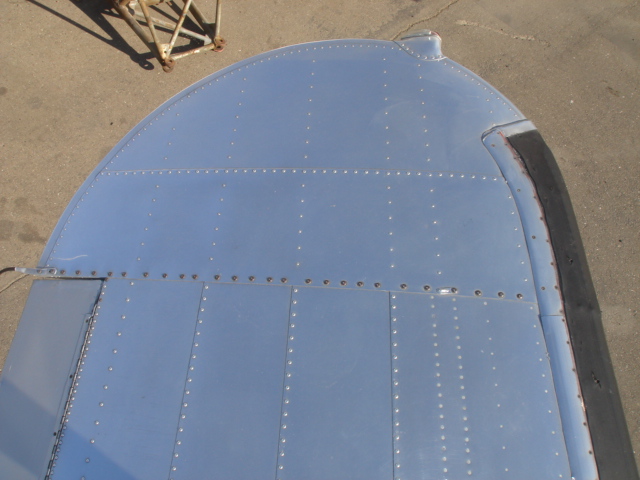
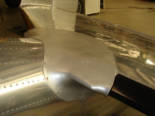
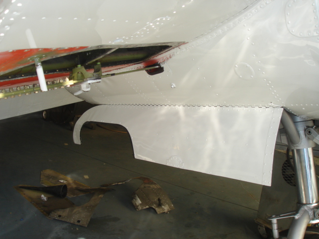
The engine nacelles differ between the C and the D and later aircraft. I have not been able to document this but my theory is that the longer nacelle was to cover up the fairing that was put in the upper wing skin because of the larger 1100-12 tires. Below are two shots that show the different length of the nacelles.
 AT-11 and C Models
This is an AT-11 nacelle which is typical of the C model aircraf t and all WWII military aircraft.
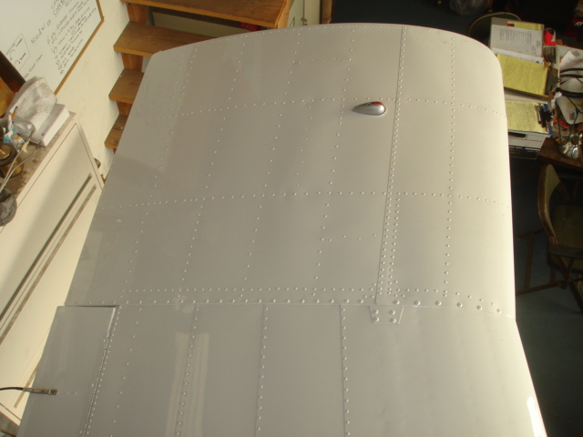
 D Models and Beyond
Notice how far back the fairing extends down the wing. The D's and later aircraft also had the leading edges changed. The leading edge contour in the C
(1945 and earlier) aircraft was straight from the tip to the fuselage. In the D and later aircraft the leading edge swept forward from the inside of the nacelle to the fuselage.
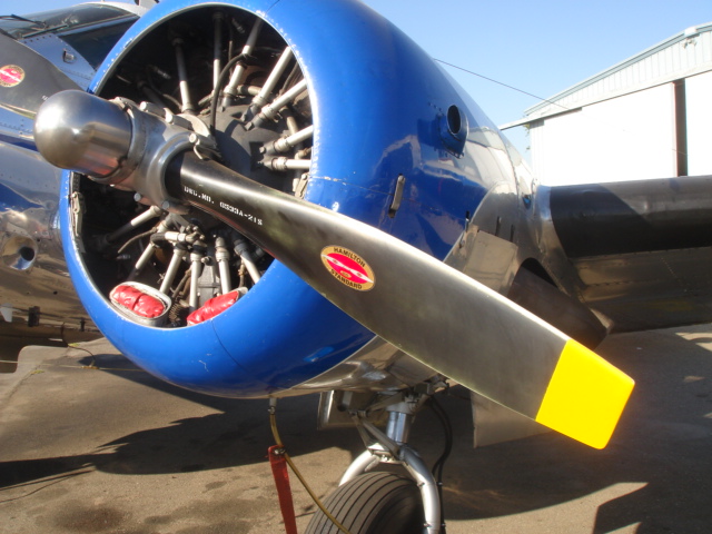
 C and D Models
This is the common carburetor intake used in the C and D model aircraft. Air entered the induction system through these scoops at the bottom of the cowling and passed
through a carb heat box where ram air could be mixed with manifold heat from the muffs around the exhaust stacks.
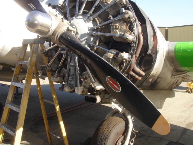
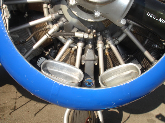
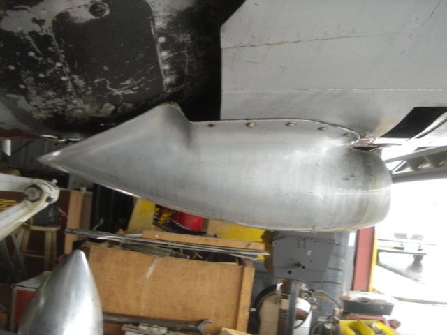
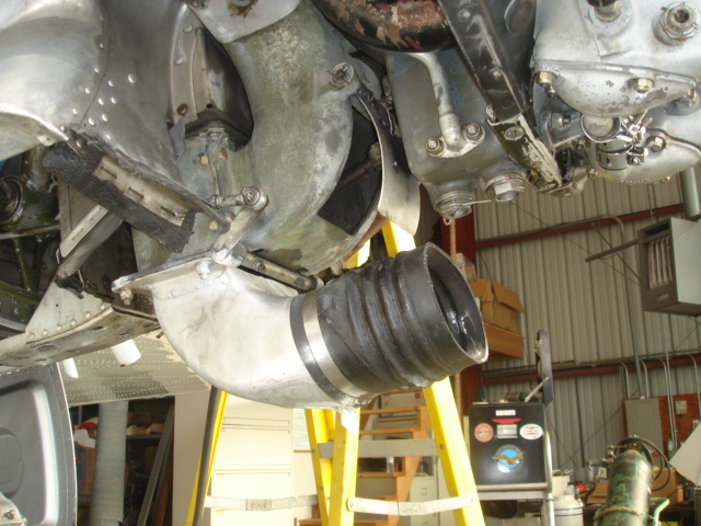
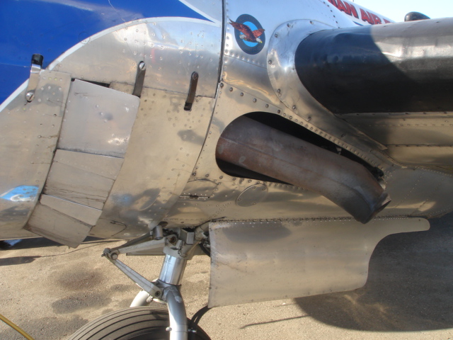
 E Models and Beyond
This Beech has a ram air scoop on the bottom of the cowling. The ram air scoop will give you quite a bit of extra "boost" which shows up later in the take
off roll. This aircraft has the modified ram air scoop and fixed cowl flaps but still retains the single exhaust stack.
 Close Up of Ram Fairing
This is a close up of the fairing over the ram air scoop on the bottom of the cowling.
 Single Stack
This is the single exhaust stack common to earlier aircraft such as the C and D models.
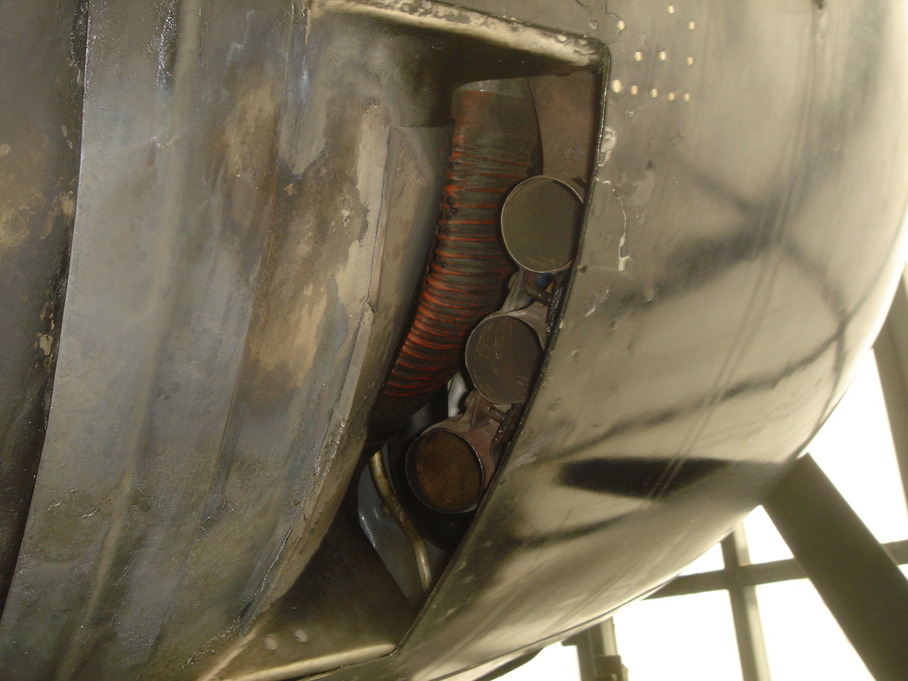
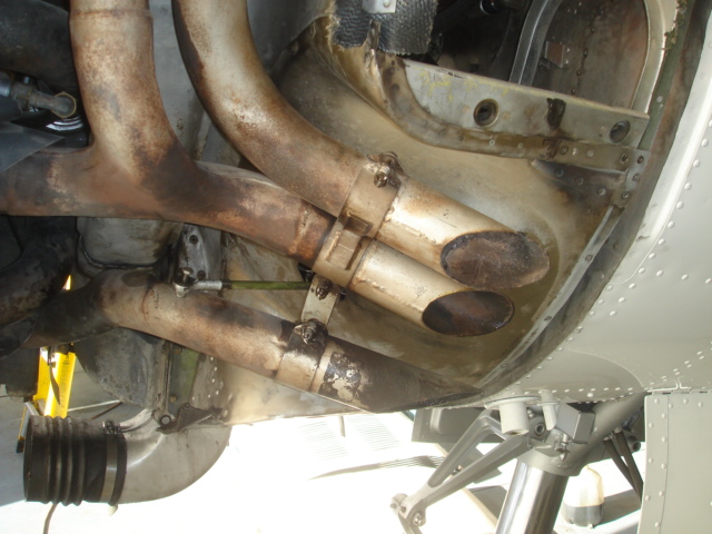 Short Stack
This is the short stack or jet stack configuration. This system was a common modification on aircraft that had gross weight STC's installed. Later aircraft had this system
from the factory and there are several types of jet stacks. Notice that this one has a late dishpan with a fixed wrapper sheet. This aircraft also has the JPI 12-1 blower STC.
There are several different types of gear doors on the various Twin Beech's. Gear doors presented problems for Beech and their customers. Maintenance was typically the cause of the problems as the early door system requires special maintenance and attention. A mechanic who installed a 1/4 inch jam nut on a clevis, that he mistakenly thought was missing, could easily cause thousands of dollars of sheet metal damage. Beech issued several service letters on this subject to try and educate their customers on proper maintenance and rigging.
 Early Gear Doors
This is the early gear door system that operated with simple 1/4 inch rods and collars clamped to the gear legs. These clamps could slip when lubricated with engine oil and vibration. One fix was to tack weld the clamps the the gear legs. The Canadian's made a clamp that was twice as long thus increasing the clamping surface area. Other things can go wrong with this system as well. More to follow...
 Later Gear Doors
This is one of the later gear door systems in which the gear doors operated independently of each other.
The early Beech's (prior to1945) would typically use a 12x5x3 Goodyear tail wheel and had a smaller lighter truss. The D's used a 14.5 SC wheel and tire.
This shot shows a comparison between the three basic tail wheel trusses. On the right is the early truss and fork found on the C model or 1945 and earlier aircraft. The one in the middle is the D and later truss and on the left is a "Tall tail wheel" truss and fork.

The early tail wheel truss was set up for the light or 7850 gross weight aircraft. The axel is a 3/8 rod and the 12x5x3 tail wheel was notched to fit the tire to prevent slipping. These tires are hard to find which is why there are very few aircraft still running them. Most early Beech's have modified their tail wheels to a different wheel and tire. Although you can bolt in a later truss it will not retract because the opening to the rear is not big enough to accept the larger 14.5 tire.
The tail wheel is supposed to have a canvas boot up in the well to keep debris out of the airframe. This boot, which cannot be easily removed, makes servicing the tail wheel truss and retract mechanism difficult. The lack of maintenance or improper maintenance can lead to the tail gear jamming. Originally when the tail gear jammed it would stop the main gear as well so they installed an aluminum bolt to shear in case the tail got stuck. It is important to be sure that you have an aluminum shear bolt installed where the retract cable attaches to the trolley on the slide tube. You can tell if the head of the bolt has a double dash on it or if a magnet will not stick to it. Make sure your mechanic knows about this. I had a bolt shear once doing a ground check and when it did it went off with a bang! I can't help but think that I should hear or feel this in flight when the gear is being cycled. So if you hear or feel a bang after the gear starts up or down you might want to suspect that the tail gear might be disconnected from the system.
The US Navy had continual troubles with their tail gear so they issued a directive requiring that all tail wheels on Twin Beech's be fixed in the down position. Beech put out a letter saying that it is a good system when maintained properly and that you should not fix it down but just maintain it properly. It is almost exactly like the letter they put out about the gear doors which to me sums up the maintenance requirements of the Twin Beech. It needs special attention by folks who know what to look for. I have seen it over and over where regular shops do the best they can but a lot of them lack the Twin Beech experience. My advice is to find yourself a mechanic who loves the Beech, and has that thirst for knowledge to learn as much as possible, then hang on to him with all you have.
This is the D tail gear next to the tall tail wheel system. On this model they simply took a regular truss and made an extension. The other model is built without the original truss and is lighter.


These two photos show the other style of tall tail wheel that is lighter than the one above. It does the same thing and weighs less.

This is a comparison shot of the original tail wheels. On the left is the 12x5x3 early wheel and tire. The middle is the 14.50 SC which stands for smooth contour. On the right is the tire available today which is squared off.
These are the same size tire (14.50) but here you can see the difference between the smooth contour, or rounded tire, and the channel type that is more squared off. The extra meat on the edges means that the tire will last longer. Depending on how much you fly the Beech can eat up tail wheel tires. The SC tires are not made any more so if you find one it will probable be over 10 years old. The tail wheel tire on a Beech is subject to side loading and possible skidding especially when the tail wheel is locked on take off and landing. All it takes is one time trying to turn off the runway with the tail wheel still locked and you will eat up the thinner rubber on the side wall eventually exposing the cords. The channel tread tires have a lot more meat on the edges so they do better in turns thus they also last longer. Save your SC tires for the judging competition and run the channel the rest of the year!
We have had a lot of problems with the new production tires with the splits in the side wall. I mostly replace tires because of these splits long before I have to change them due to wear on the treads. Manufacturers say that splits are okay if it doesn't reach the cord. I have seen splits right next to the wheel that run deep.
Many folks have installed other wheels on the tail since the tires are hard to find and are expensive. I have seen Cessna wheels and other surplus wheels used. Cleveland has an STC for their own wheel that uses a common tire.
Below are a series of photos showing the different types of door configurations you can have with your Beech. It is possible to change the configuration from say a round door to a cargo door, but obviously takes time with restructuring and reskinning the area.

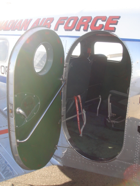 Round Doors
These doors are typically found on C model aircraft. Some had an inner door within the round door, that would open to the inside during flight, for recon and photography. during the War.
 Round Door with the Cargo Door
This is a rare configuration you don't see too often anymore, and was also on earlier models of the Beech. The round door could open independently from the cargo door.
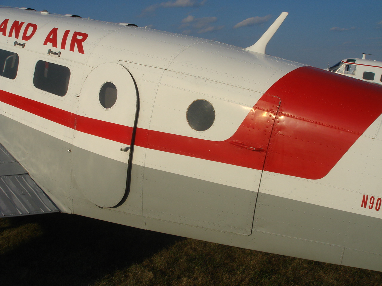
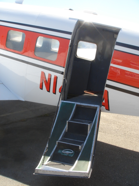
 Rounded Air Stair Door
While the air stair door is common among the later models, the rounded air stair door is not so common. But, this did make it a lot easier to enter the aircraft, and is best used for transporting people or doing air charter.
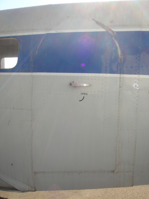
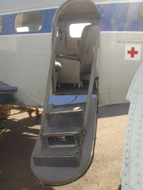
 Squared Air Stair Door
This is the more common look for later model air stair doors, and the one you will most likely see with aircraft meant for civilian transport.
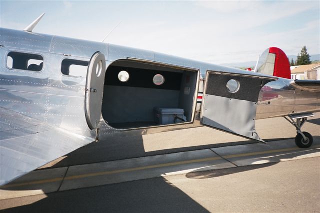
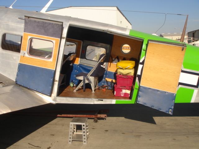 Full Cargo Doors
This configuration is also indicative of an older model aircraft, such as the c or d model. The cargo doors open one at a time; first the left then the right. Very useful for hauling cargo, or as we used it for, hauling our air show equipment or our family roadtrip supplies.
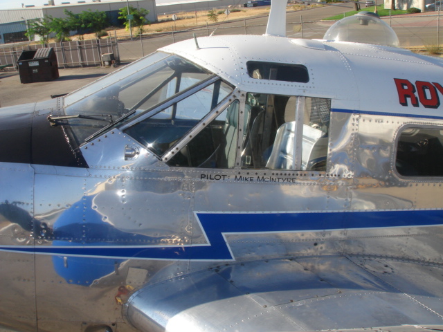
 Standard Glass
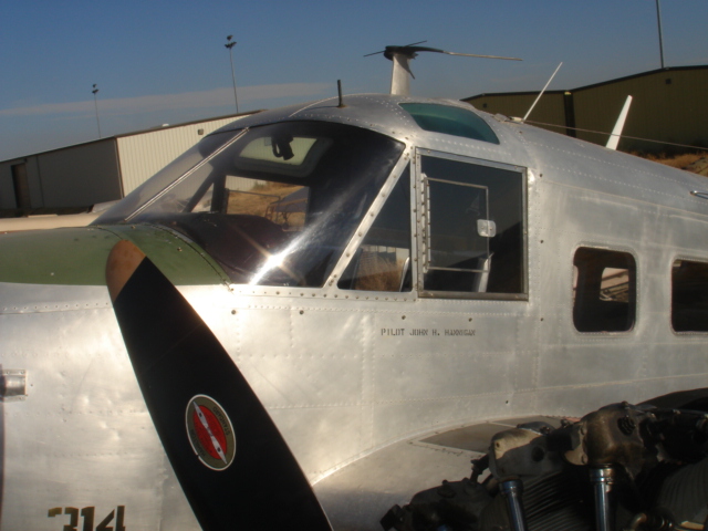 Two Piece Windshield
This page didn't technically have an end, as it's still in progress, but for now we'll say that this scratches the surface on what we mean when we say the Beech is a very versatile aircraft, and one that can and will fit your needs, as long as you have the patience and the dream for it.